
Start with the circuit you are switching or watching, not the name of the equipment on the drawing. Write down how many separate circuits sit at that position, what voltage and current each carries, and whether the fire alarm sends a command out, reads a signal back, or does both. A lift, a damper and a smoke vent all reduce to the same short list, and you choose from it.
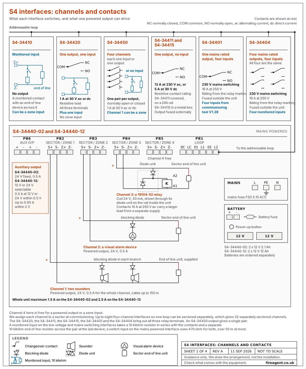
Count the input and output circuits, then map them to the channels and modes of the interface you choose. Voltage, current and the type of load give the rating. How the outputs have to be sectored, that is which of them the panel operates together on a fire event, settles how the channels are commissioned. The panel on site decides what the loop will accept. There is one more thing to establish: whether the circuit is a zone of conventional detectors and call points, or a pair of voltage free contacts that carry no supply of their own. Only part of the range takes a zone.
How many circuits can one Gent fire alarm interface unit handle?
One interface covers between one and four channels, and the mains powered units take up to eight circuits across their four channels. Count the circuits at a single position, then match what each has to switch or monitor to the ratings below.
| Interface | Circuits | What it switches or monitors | Rating | Sectoring |
|---|---|---|---|---|
| S4-34410 | One input | Voltage free contacts, or a conventional detector zone | No output | No output to sector |
| S4-34420 | One output, one input | One relay circuit, the input watching the equipment it operates | 1 A at 30 V, alternating or direct current, resistive | Sectored on its own |
| S4-34450 | Four channels, input or output | Relay circuits, indicator circuits, contacts, and a zone on channel one | 1 A at 30 V, alternating or direct current, resistive, per relay output; an indicator output 1.5 mA at 24 V direct current | Set per channel at commissioning |
| S4-34411 | One output, no input | One direct current circuit, switched not watched | 5 A at 30 V direct current, resistive; the contacts are also rated 12 A at 230 V alternating current; external fusing of the output required | One output |
| S4-34415 | One output, no input | The same circuit, boxed | The same ratings as the S4-34411; external fusing of the output required | One output |
| S4-34401 | One mains rated output, four inputs from commissioning tool V1.28 | One 230 V circuit, four monitored contacts, and a zone on channel one if set that way | 230 V mains switching, contacts rated 16 A at 250 V; external fusing required | Output uses channel one |
| S4-34404 | Four mains rated outputs, four inputs | Four 230 V circuits and four monitored contacts | The same ratings as the S4-34401 | Each output can be sectored on its own |
| S4-34440-02 | Four channels, up to eight circuits | Powered 24 V circuits, contacts, or a zone on any channel | 0.5 A per output at 24 V, 1.5 A total | Set per channel at commissioning |
| S4-34440-12 | Four channels, up to eight circuits | The same as the -02 | 0.5 A per output at 24 V, 2.5 A total | Set per channel at commissioning |
The S4-34420 brings out all three relay terminals, normally closed, common and normally open, while an S4-34450 output channel gives a single pair.
The low voltage interfaces and the mains switching pair all take their working power from the detection loop, along with the address the panel knows them by. The S4-34401 and S4-34404 additionally switch an external 230 V supply, fused outside the unit. A monitored input run is limited to 300 m on the S4-34410, S4-34420 and S4-34450, and to 50 m on the mains switching interfaces and on the S4-34440-02 or -12 switch inputs.
How do I assign outputs to sectors so the panel operates the right ones together?
We assign each output to a sector at commissioning, which is where the fire alarm cause and effect is set. Every output starts in sector one, and an interface driving plant goes into a plant sector. Two outputs sharing a sector always act as one, so an output that has to run alone needs a sector of its own.
A loop carries up to 200 low voltage interfaces with relay outputs. Up to eight of the four-channel units on that loop, S4-34450 or the S4-34440 range, can be sectored, and every channel on those eight can take a sector of its own, so one loop offers 32 separately sectored channels before a second loop is needed.
Where two commands must run separately, two S4-34420 interfaces do it with one output each and are the simpler of the two to program; an S4-34450 does the same on one address with its channels sectored separately.
Return signals need counting at the same time. A confirmation input is tied to an output, so the panel is told the equipment moved and raises a fault if that change of state does not arrive in time. The S4-34420 carries its own; on the S4-34450 a confirmation takes a second channel, so two commands and two returns use all four channels.
Which interfaces take a zone of conventional detectors?
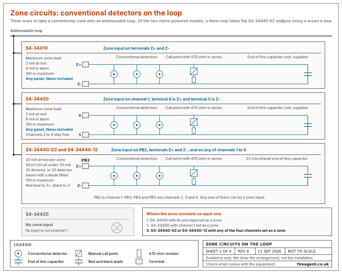
Three interfaces take a zone of conventional detectors and call points: the S4-34410 on its one input, the S4-34450 on channel one, and the S4-34440-02 or -12 on any of its four channels. Those first two work on every panel including Nano, while a Nano loop takes the S4-34440-02 only. The S4-34420 does not take a zone, because a zone has to sit on channel one and its input is not channel one. This decides the interface wherever an existing conventional circuit is brought onto an addressable loop.
On the S4-34410 and the S4-34450 the zone ends in the end-of-line capacitor unit supplied with the interface, the part that lets the panel see a break in the wiring. Every call point takes a 470 ohm resistor or a 3.9 V Zener diode in series with its normally open contacts. The maximum zone load is 2 mA at rest and 9 mA in alarm, the run reaches 100 m, and a loop takes 30 zone inputs at most.
Any of the four channels on the S4-34440 range can be a zone instead, drawing about 20 mA at rest, with the current held below 30 mA on a short circuit. A zone there carries 32 devices, or up to 20 detector bases with a diode fitted, and ends in a 22 microfarad end-of-line capacitor at the last device, with a 470 ohm resistor in series with each call point; the run can be 150 m.
Can I connect intrinsically safe detectors and sounders?
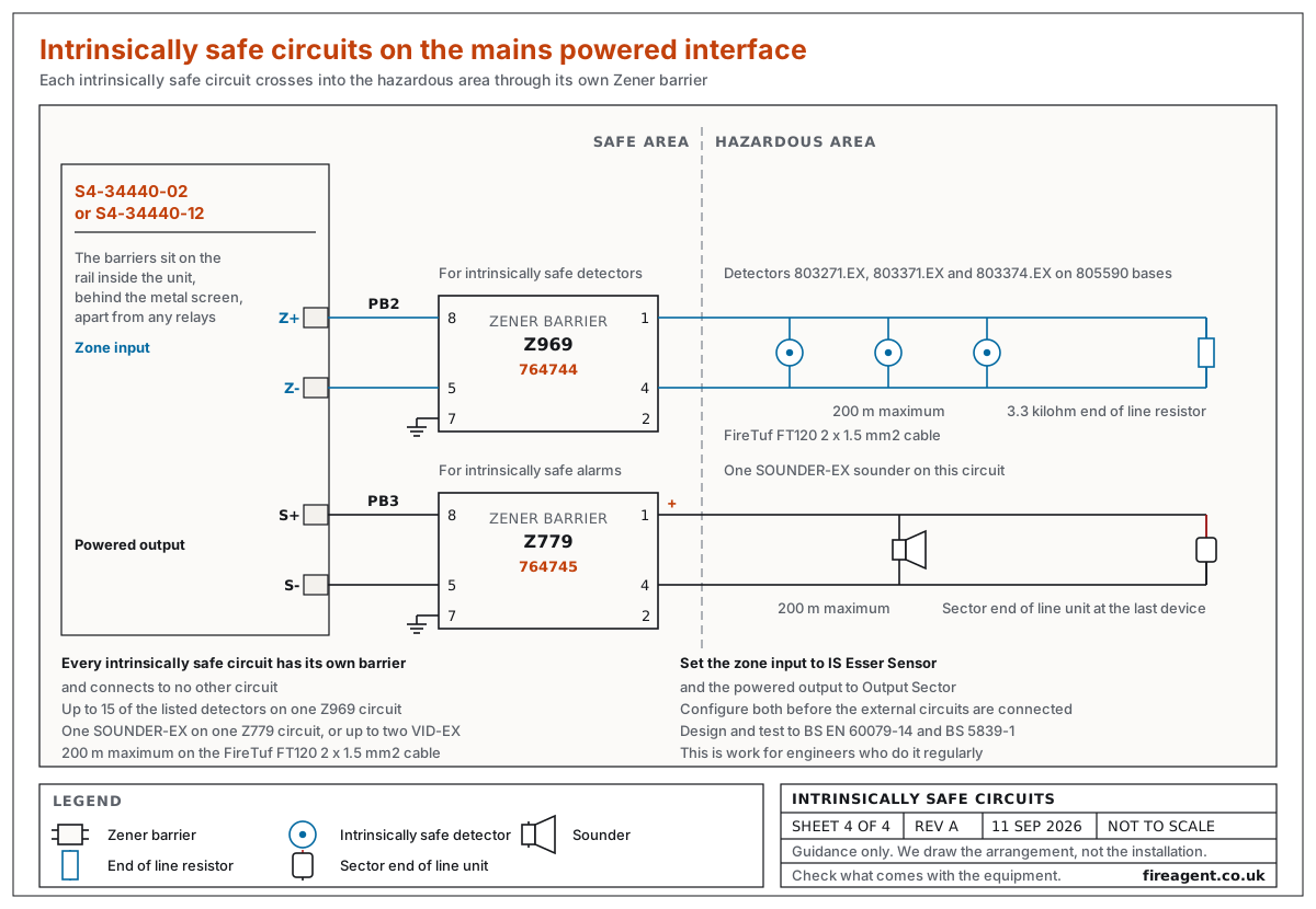
Yes, through the mains powered interface, with a Zener barrier on each circuit to cap the voltage and current crossing into the hazardous area. Detectors sit on a zone input behind a Z969 barrier, part number 764744, ending in a 3.3 kilohm end-of-line resistor in the hazardous area. Sounders and visual alarm devices, which are the flashing beacons, run from a sector output behind a Z779 barrier, part number 764745, ending in the sector end-of-line unit. Each circuit reaches 200 m.
We supply the 803271.EX heat detector, the 803371.EX optical smoke detector and the 803374.EX multisensor on the 805590 base, with the SOUNDER-EX sounder and the VID-EX visual alarm device.
A barrier connects to nothing but its own circuit. The barriers mount on the rail inside the interface, apart from the power relays and behind the metal screen. FireTuf FT120 is the cable we put on these circuits. Design and testing belong to engineers working to BS EN 60079-14 and BS 5839-1.
Each barrier has a limit. A Z969 circuit takes up to fifteen of the detectors we list; a Z779 circuit takes one SOUNDER-EX, or up to two VID-EX beacons, never both on one barrier; every intrinsically safe run stays within 200 m of the FireTuf FT120 cable. Set the detector zone to IS Esser Sensor and the alarm output to Output Sector before the external circuits are connected.
When do I need a mains powered interface?
You need one when the equipment you are operating has no supply of its own. The S4-34440 range carries a battery backed 24 V power supply alongside its four channels, so its outputs feed the equipment rather than closing a contact in another circuit. Each powered output delivers up to 0.5 A at 24 V. A powered output set to be monitored ends in the sector end-of-line unit supplied with the interface and takes a series blocking diode, whether it drives a sounder, a visual alarm device, a door holder or a relay. An output driving a relay coil takes a diode across that coil as well. An output set to be unmonitored, which is only for a legacy galvanic isolator, needs neither the end-of-line unit nor the diode.
The two models differ in their auxiliary output and in their total capacity. That auxiliary output, which supplies external equipment beside the switched circuits, is fixed at 24 V and 0.5 A on the S4-34440-02. Its equivalent on the -12 is regulated, can be set to 12 V or 24 V, and gives 0.5 A at a tight tolerance or up to 0.65 A at a wider one. Total output is 1.5 A on the -02 and 2.5 A on the -12, the auxiliary load counted inside that total.
Standby batteries are ordered separately and are not shared between the models: two 12 V 2.1 Ah on the -02, two 12 V 12 Ah on the -12. Of the two mains powered models, a Nano loop takes the -02 only.
Fail safe operation can be set on the sectored outputs: if loop communication is lost for longer than the period set for it those outputs switch on, and switch off again when it returns.
How do I drive a large sounder load?
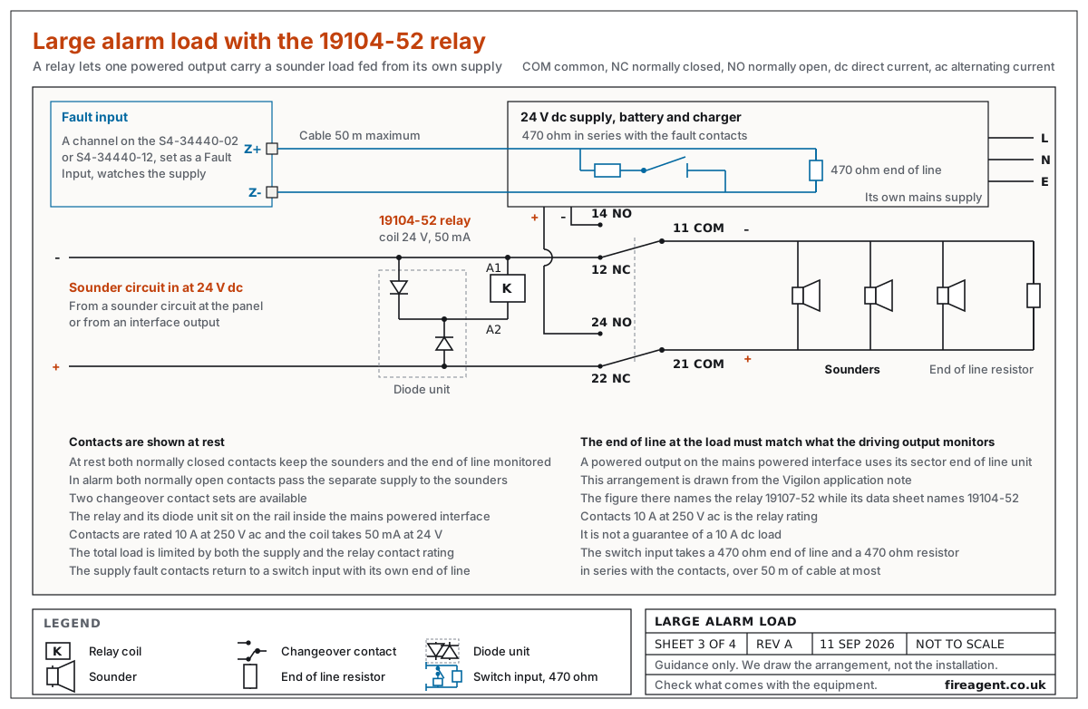
A fire alarm relay and a separate power supply do it, so the sounders take their current from that supply, not from the fire alarm output. The 19104-52 power relay is the part we use: a 24 V coil of 470 ohms drawing 50 mA, and an eight pin base that clips to a rail. Contacts are rated 10 A at 250 V ac; the permitted load on direct current is established for the actual sounder circuit before the relay is specified.
The monitored 24 V sounder circuit from the panel or an interface drives the relay coil through a diode unit on the same rail. A separate 24 V battery backed supply, on its own mains feed, is then switched through the relay contacts to the chain of sounders, which ends in an end-of-line resistor. That supply also has fault contacts, taken to an interface input.
The relays and their diode units mount on the rail inside a mains powered interface, apart from any Zener barriers and behind the metal screen. This arrangement has been used on large industrial sites where the sounders are too heavy for a panel circuit. The load must stay within the rating of the separate supply and within the rating of the relay contacts.
What connects to a Gent interface: AOVs, lifts, dampers, plant and the ARC?
Any clean contact can signal this equipment, so the choice is never the equipment name. It is the count of circuits, the rating and how the outputs are sectored. Ask how many separate circuits the equipment needs, what each switches or monitors, and what voltage and current each carries.
- AOV smoke vents, the automatic opening vents, connect to a Gent interface through their controller. The controller takes a command to open and returns a signal once the vent has moved, so count the command and the return as separate circuits.
- Lifts connect through the lift controller. Sending the car to the ground floor alone needs one contact, and adding an alternative floor needs two. The lift company confirms which applies.
- Dampers connect through their actuators or controller. They are often sectored by area, each with a return signal, so establish which operate together and which need a sector of their own.
- Plant shutdown connects to the ventilation and fuel valve controls. They take either a contact or an external supply switched through the interface, so settle which before counting circuits.
- Fire alarm door holders and other held open door hardware connect through a mains powered interface. Run from that interface, they need an EN Vigilon panel with main controller card V4.48 to meet BS 7273 Part 4:2007; a BS Vigilon or a Nano panel cannot provide it.
- Sprinkler flow switches connect to a monitored input. Count the flow and pressure switches to be monitored, and note whether each set of contacts is normally open or normally closed.
- ARC, the alarm receiving centre, connects through the alarm transmission equipment on site. That equipment defines what it needs to see, so confirm the number of contacts, their form and their rating with its supplier.
How do I order the right interface?
Send us the part numbers if you have them, or the circuit schedule if you do not: the circuits at each position, what each switches or monitors, their ratings, how the outputs have to be sectored, and which panel the loop belongs to. Return signals count as circuits.
Enclosures are separate order lines for the interfaces that come without one. The S4-34410, S4-34420 and S4-34450 arrive without a box, the S4-34411 is a covered interface for a DIN rail inside other equipment, and the rest come housed. Tell us where each interface goes and we will add the right housing to the quotation.
What else do people ask before they order?
Questions to check before ordering.
Does the S4-34410 have a relay output?
No, it is an input only interface. It reads one circuit of voltage free contacts, set as a fire, fault or supervisory input, and reports open and short circuit faults in every mode. Where a command must go out, use the S4-34420.
Can I put conventional detectors on a Gent addressable loop?
Yes, on three of the interfaces, with the conventional circuit wired in as a zone. Two of them are low voltage units that come with the capacitor terminating the zone, work on any panel, and hold the run inside 100 m. The third is the mains powered interface, which gives you 150 m and a choice of four channels.
What is the difference between the S4-34440-02 and the S4-34440-12?
The S4-34440-12 gives more total current, takes larger batteries and has an auxiliary output you can set to 12 V or 24 V, while the -02 auxiliary is fixed at 24 V. Both give 0.5 A per powered output at 24 V, but the -02 totals 1.5 A against 2.5 A, and only the smaller unit fits a Nano loop.
How many outputs can be sectored separately on one loop?
Thirty two, before a second loop is needed. That is eight four-channel units, either the S4-34450 or the S4-34440 range, each with its four channels in a sector of its own. A loop has 207 device addresses, and within that no more than 200 interfaces set with switch inputs and no more than 200 set with relay outputs. Count the commands that genuinely have to run in isolation before you count interfaces.
Do the mains switching interfaces power the equipment they operate?
They do not. The S4-34401 and S4-34404 take their electronics off the loop and switch an external 230 V supply through contacts rated 16 A at 250 V, fused outside the unit. Where the equipment has no supply, the S4-34440 range feeds its outputs at 24 V.
Can one interface handle two commands and both return signals?
Yes, an S4-34450 does it on one address, two channels as outputs and two as confirmation inputs, which uses all four of its channels. Two S4-34420 interfaces cover the same work with one output and one input each, and each interface is then sectored on its own.
Do I need a separate barrier for each intrinsically safe circuit?
Every intrinsically safe circuit into the hazardous area takes its own Zener barrier, which serves no other circuit. Detectors go through a Z969, part number 764744; sounders and visual alarm devices through a Z779, part number 764745. Each barrier lets its circuit be monitored by an end-of-line component. There is a limit on how many devices one barrier will carry, so send us the device count on each circuit and we will confirm it.


